|
Stepper-Motor-Control
v3.0.0
System on a Chip 2014 - Group 04
|
Milestone 3. More...
Libraries | |
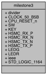
| ieee | |
| Use Standard Library. | |
Use Clauses | |
| STD_LOGIC_1164 | |
| Use Logic Elements. | |
Generics | |
| divider | integer := 125000 |
| Prescaler for PWM-signal. | |
Ports | |
| CLOCK_50_B5B | in STD_LOGIC |
| component clock | |
| CPU_RESET_n | in STD_LOGIC |
| resets the component | |
| SW | in STD_LOGIC_VECTOR ( 9 DOWNTO0 ) |
| switch input | |
| KEY | in STD_LOGIC_VECTOR ( 3 DOWNTO0 ) |
| key input | |
| HSMC_RX_P | out STD_LOGIC_VECTOR ( 16 DOWNTO0 ) |
| Motor_pwm1( bit 0 ) and Motor_pwm2( bit 1 ) | |
| HSMC_RX_N | out STD_LOGIC_VECTOR ( 16 DOWNTO0 ) |
| Motor_pwm3( bit 0 ) and Motor_pwm4( bit 1 ) | |
| HSMC_TX_N | out STD_LOGIC_VECTOR ( 16 DOWNTO0 ) |
| Motor_en_a( bit 2 ) | |
| HSMC_TX_P | out STD_LOGIC_VECTOR ( 16 DOWNTO0 ) |
| Motor_en_b( bit 3 ) | |
| LEDG | out STD_LOGIC_VECTOR ( 7 DOWNTO0 ) |
| green leds | |
| LEDR | out STD_LOGIC_VECTOR ( 7 DOWNTO0 ) |
| red leds | |
Milestone 3.
Definition at line 35 of file milestone3.vhd.
|
Generic |
Prescaler for PWM-signal.
For this purpose 2,5 ms are used as minimal pulse-width.
The prescaler is calculated with the given and desired frequency via the following formula:
\begin{equation*} \text{prescaler} = \frac{f_{\text{clock}} \text{Hz}}{f_{\text{prescaler}} \text{Hz}} \end{equation*}
e.g.:
\begin{equation*} \left.\begin{aligned} f_{\text{prescaler}} &= \frac{5}{2}\,\text{ms} \newline &= 400\,\text{Hz} \newline\newline \text{prescaler} &= \frac{50\,\text{Mhz}}{400\,\text{Hz}} \newline &= 125000 \newline \end{aligned} \right\} \qquad \text{pulse-width: 2.5 ms} \end{equation*}
For simulation-purpose the divider was set to 125 for faster wave generation.
Definition at line 58 of file milestone3.vhd.
 1.8.8
1.8.8 
